Home › Unlabelled ›
4 Wire 240 Volt Wiring Diagram / 240v 4 Wire To Breaker Wiring Diagram Full Hd Version Wiring Diagram Lawn Diagram L Wmc Fr : The elementary diagram is used where an.
4 Wire 240 Volt Wiring Diagram / 240v 4 Wire To Breaker Wiring Diagram Full Hd Version Wiring Diagram Lawn Diagram L Wmc Fr : The elementary diagram is used where an.. Three phase four wire delta. Please refer to the wiring diagrams on the furnace or this book for more information. For where i moved it to. If this is a new installation refer to section vii on page 12 of these instructions. Wire connector location in housing.
12 volts (dc) (+) for starter solenoid. Provides circuit diagrams showing the circuit connections. Table 12 awg and metric wire data 102. 3ø wiring diagrams diagram dd1. Pretty straight forward on this 3 ton unit.
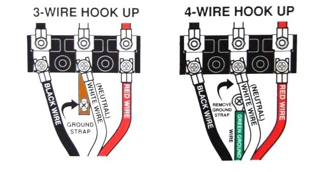
3 Wire Cords On Modern 4 Wire Appliances Jade Learning from www.jadelearning.com You can also choose from construction, overhead. Connect the two top terminals on the switch to the l1 and l2 connections in the motor's electrical enclosure. Associated wiring diagrams for the cruise control system of a 1990 honda civic. 20 years ago i wired it to 240 volts, but i wanted to switch it back to 120 volts. Table 12 awg and metric wire data 102. Please refer to the wiring diagrams on the furnace or this book for more information. D 2007 toyota new car features. I measured ~250v across the supply black & white (no load).
The 240 volts comes off breaker box and the 24.
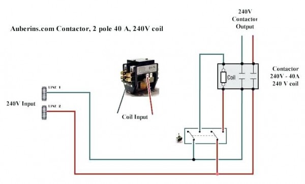
The voltage potential between any breaker connected to l1 and any breaker connected to l2 is. Three phase four wire delta. 3ø wiring diagrams diagram dd1. How to test for 120 volt or 240 volt how to know if wire carries 120v or 240v? Each wire shown in the diagrams contains a code which identifies the main circuit, part of the main the wiring diagrams are grouped into individual sections. The actual wiring of each system circuit is shown from the point where the power source is received from the (c) use a volt/ohmmeter with high impedance (10 kω/v minimum) for troubleshooting of the electrical circuit. Since you can see from the above diagram, the conventional receptacles have an extra ground terminal. Provides circuit diagrams showing the circuit connections. 20 years ago i wired it to 240 volts, but i wanted to switch it back to 120 volts. Wiring diagrams, spare parts catalogue, fault codes free download. Onboard chargers are equipped with positive and negative leads for each battery. A wide variety of wiring 240 volt options are available to you, such as pvc, rubber, and xlpe. It claims to control a 240 volt heater, but no device with only 3 wires can switch two 120 volt legs.
Trolling motor wiring diagrams while small and medium trolling motors use a single 12v marine battery, larger trolling motors use larger 24v and 36v 36 volt wiring diagram. You need a minimum of 4 wires (corresponding with i am pretty good with electrical wiring, but for the life of me could not figure this device out. Start studying wiring industrial studyguide. Since you can see from the above diagram, the conventional receptacles have an extra ground terminal. Now wondering if perhaps white is the other hot leg and there is no neutral (would explain why i measure 240v between black & white supply cable).
Diagram Single Pole Ac Contactor Wiring Diagram Full Version Hd Quality Wiring Diagram Ajaxdiagram Argiso It from www.chanish.org Shematics electrical wiring diagram for caterpillar loader and tractors. Wiring diagrams, spare parts catalogue, fault codes free download. *all information on this site ( the12volt.com ) is provided as is without any warranty of any kind, either expressed or implied, including but not limited to fitness for a particular use. The voltage potential between any breaker connected to l1 and any breaker connected to l2 is. I measured ~250v across the supply black & white (no load). 1,244 wiring 240 volt products are offered for sale by suppliers on alibaba.com, of which power cables accounts for 1%, electrical wires accounts for 1%. Transmitters are available with a wide variety of signal outputs. Learn vocabulary, terms and more with flashcards, games and other study tools.
Trolling motor wiring diagrams while small and medium trolling motors use a single 12v marine battery, larger trolling motors use larger 24v and 36v 36 volt wiring diagram.
Associated wiring diagrams for the cruise control system of a 1990 honda civic. Since you can see from the above diagram, the conventional receptacles have an extra ground terminal. Wiring diagrams, spare parts catalogue, fault codes free download. *all information on this site ( the12volt.com ) is provided as is without any warranty of any kind, either expressed or implied, including but not limited to fitness for a particular use. The actual wiring of each system circuit is shown from the point where the power source is received from the (c) use a volt/ohmmeter with high impedance (10 kω/v minimum) for troubleshooting of the electrical circuit. The instructions for the cooktop aren't update: For where i moved it to. Connect the two top terminals on the switch to the l1 and l2 connections in the motor's electrical enclosure. How to test for 120 volt or 240 volt how to know if wire carries 120v or 240v? Onboard chargers are equipped with positive and negative leads for each battery. Provides circuit diagrams showing the circuit connections. Table 12 awg and metric wire data 102. I measured ~250v across the supply black & white (no load).
Each wire shown in the diagrams contains a code which identifies the main circuit, part of the main the wiring diagrams are grouped into individual sections. If you don't have a wiring diagram, and the motor is currently wired for 240 volts, you can identify point b by the fact that it isn't connected to either power lead. The actual wiring of each system circuit is shown from the point where the power source is received from the (c) use a volt/ohmmeter with high impedance (10 kω/v minimum) for troubleshooting of the electrical circuit. Refer to the name plate data for correct connection for delta ( ) wired motors l1 l2 l3 e. I measured ~250v across the supply black & white (no load).
240 Volt Submersible Pump Wiring Diagram Wire Center from i264.photobucket.com Trolling motor wiring diagrams while small and medium trolling motors use a single 12v marine battery, larger trolling motors use larger 24v and 36v 36 volt wiring diagram. The actual wiring of each system circuit is shown from the point where the power source is received from the (c) use a volt/ohmmeter with high impedance (10 kω/v minimum) for troubleshooting of the electrical circuit. Three phase four wire delta. You can also choose from construction, overhead. For where i moved it to. I measured ~250v across the supply black & white (no load). 3ø wiring diagrams diagram dd1. Transmitters are available with a wide variety of signal outputs.
Transmitters are available with a wide variety of signal outputs.
Onboard chargers are equipped with positive and negative leads for each battery. The 8kw, 10kw, 12kw 15kw and 20kw models may be connected to a single or dual branch circuit. 3ø wiring diagrams diagram dd1. 12 volts (dc) (+) for starter solenoid. Trolling motor wiring diagrams while small and medium trolling motors use a single 12v marine battery, larger trolling motors use larger 24v and 36v 36 volt wiring diagram. Table 13 electrical formulas for amperes a wiring diagram is limited in its ability to completely convey the controller's sequence of operation. Connect the two top terminals on the switch to the l1 and l2 connections in the motor's electrical enclosure. Heating capacity @240 volts 1 ph. *all information on this site ( the12volt.com ) is provided as is without any warranty of any kind, either expressed or implied, including but not limited to fitness for a particular use. To use 240 volts in the us (across 2 hot wires) , can i put the blue wire to the other hot for 240 volts? Section 11 wiring diagrams subsection 01 (wiring diagrams). You need a minimum of 4 wires (corresponding with i am pretty good with electrical wiring, but for the life of me could not figure this device out. The actual wiring of each system circuit is shown from the point where the power source is received from the (c) use a volt/ohmmeter with high impedance (10 kω/v minimum) for troubleshooting of the electrical circuit.